- 您现在的位置:买卖IC网 > Sheet目录3833 > AT87251G2D-3CSUM (Atmel)IC 8051 MCU 32K OTP 24MHZ 40DIP
30
AT/TSC8x251G2D
4135F–8051–11/06
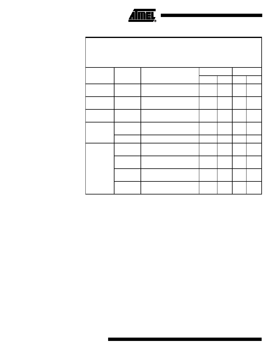
Table 25.
Summary of Move Instructions (1/3)
Notes: 1. A shaded cell denotes an instruction in the C51 Architecture.
2. Extended memory addressed is in the region specified by DPXL (reset value = 01h).
3. If this instruction addresses external memory location, add N+1 to the number of
states (N: number of wait states).
4. If this instruction addresses external memory location, add N+2 to the number of
states (N: number of wait states).
Move to High wordMOVH <dest>, <src>dest opnd31:16 ← src opnd
Move with Sign extensionMOVS <dest>, <src>dest opnd
← src opnd with sign extend
Move with Zero extensionMOVZ <dest>, <src>dest opnd
← src opnd with zero extend
Move CodeMOVC A, <src>(A)
← src opnd
Move eXtendedMOVX <dest>, <src>dest opnd
← src opnd
Mnemonic
<dest>,
<src>
(2)
Comments
Binary Mode
Source Mode
Bytes
States
Bytes
States
MOVH
DRk, #data16
16-bit immediate data into upper
word of dword register
53
4
2
MOVS
WRj, Rm
Byte register to word register with
sign extension
32
2
1
MOVZ
WRj, Rm
Byte register to word register with
zeros extension
32
2
1
MOVC
A, at A +DPTR
Code byte relative to DPTR to
ACC
16(3)
A, at A +PC
Code byte relative to PC to ACC
1
6(3)
16(3)
MOVX
A, at Ri
Extended memory (8-bit address)
to ACC(2)
14
1
5
A, at DPTR
Extended memory (16-bit
address) to ACC(2)
13(4)
at Ri, A
ACC to extended memory (8-bit
address)(2)
14
1
4
at DPTR, A
ACC to extended memory (16-bit
address)(2)
14(3)
发布紧急采购,3分钟左右您将得到回复。
相关PDF资料
AT80C51RA2-SLSUM
IC 8051 MCU ROMLESS 44PLCC
AT80C51RA2-SLSUL
IC 8051 MCU ROMLESS 44PLCC
AT80C51RA2-RLTUM
IC 8051 MCU ROMLESS 44VQFP
213931-5
CONN JACKSCREW RECEPT 34 POS
AT80C51RA2-RLTUL
IC 8051 MCU ROMLESS 44VQFP
AT80C51RA2-3CSUM
IC 8051 MCU ROMLESS 40DIP
AT80C51RA2-3CSUL
IC 8051 MCU ROMLESS 40DIP
AT80C31X2-SLSUM
IC 8031 MCU ROMLESS 44PLCC
相关代理商/技术参数
AT87251G2D-RLTUL
制造商:ATMEL 制造商全称:ATMEL Corporation 功能描述:B/16-BIT MICROCONTROLLER WITH SERIAL COMMUNICATION INTERFACES
AT87251G2D-RLTUM
功能描述:8位微控制器 -MCU 251G2D 8/16bitC OTP 5V RoHS:否 制造商:Silicon Labs 核心:8051 处理器系列:C8051F39x 数据总线宽度:8 bit 最大时钟频率:50 MHz 程序存储器大小:16 KB 数据 RAM 大小:1 KB 片上 ADC:Yes 工作电源电压:1.8 V to 3.6 V 工作温度范围:- 40 C to + 105 C 封装 / 箱体:QFN-20 安装风格:SMD/SMT
AT87251G2D-SLSUL
功能描述:8位微控制器 -MCU Microcontroller
RoHS:否 制造商:Silicon Labs 核心:8051 处理器系列:C8051F39x 数据总线宽度:8 bit 最大时钟频率:50 MHz 程序存储器大小:16 KB 数据 RAM 大小:1 KB 片上 ADC:Yes 工作电源电压:1.8 V to 3.6 V 工作温度范围:- 40 C to + 105 C 封装 / 箱体:QFN-20 安装风格:SMD/SMT
AT87251G2D-SLSUM
功能描述:8位微控制器 -MCU OTP 8/16bit St 5V 24MHz RoHS:否 制造商:Silicon Labs 核心:8051 处理器系列:C8051F39x 数据总线宽度:8 bit 最大时钟频率:50 MHz 程序存储器大小:16 KB 数据 RAM 大小:1 KB 片上 ADC:Yes 工作电源电压:1.8 V to 3.6 V 工作温度范围:- 40 C to + 105 C 封装 / 箱体:QFN-20 安装风格:SMD/SMT
AT875
制造商:POSEICO 制造商全称:POSEICO 功能描述:PHASE CONTROL THYRISTOR
AT875LT
制造商:POSEICO 制造商全称:POSEICO 功能描述:PHASE CONTROL THYRISTOR
AT875LTS44
制造商:POSEICO 制造商全称:POSEICO 功能描述:PHASE CONTROL THYRISTOR
AT875S44
制造商:POSEICO 制造商全称:POSEICO 功能描述:PHASE CONTROL THYRISTOR